Eliminating Glass Anisotropy: A Key Step Toward Perfect Architectural Glass

Introduction
Modern architecture continuously raises the standard for building materials, especially for one of the most admired and visually striking elements in construction—glass. Today, glass is no longer simply a transparent material; it represents luxury, protection, innovation, and sustainability. Architects and project stakeholders increasingly demand glass that is visually flawless while maintaining all structural and functional performance. Advances in glass manufacturing have significantly improved optical purity and surface quality, enabling the industry to create new standards for architectural glazing. However, when selecting glass for building facades, two major optical challenges remain: anisotropy and roller wave distortion. Roller wave distortion can typically be controlled by optimizing the tempering furnace parameters, such as heating temperature, cooling speed, and air distribution. Anisotropy—commonly known as the “leopard spot” effect—is caused by stress birefringence and becomes visible under certain lighting and viewing conditions. International standards such as ASTM C1048, EN 1863, EN 12150, and EN 14179 describe anisotropy as an inherent optical characteristic rather than a defect. After years of technological development, new tempering technologies have significantly reduced visible anisotropy in fully tempered glass and heat‑strengthened glass, providing architects with improved optical clarity for high‑end glass facades.
Understanding Glass Anisotropy
Origin of Anisotropy
Float glass is typically considered optically isotropic due to the controlled annealing process during manufacturing. In isotropic materials, light travels through the glass with the same refractive index in all directions. However, internal stresses introduced during the tempering process can cause the material to behave anisotropically. When polarized light passes through stressed glass, birefringence occurs, meaning the light splits into two components traveling at different speeds. This results in visible interference patterns known as anisotropy or “leopard spots.”The tempering process involves heating glass above its glass transition temperature (Tg) and then rapidly cooling it using high‑pressure air jets. Because perfect heating uniformity is difficult to achieve, factors such as:
- Roller contact points
- Glass geometry
- Holes or cutouts
- Edge shapes
can create uneven heating and cooling conditions. These variations produce residual stress patterns within the glass, which remain permanently “frozen” after tempering and lead to optical anisotropy.
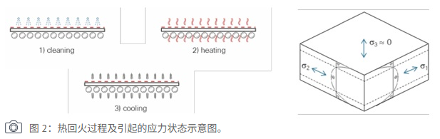
Figure 2. Schematic of the glass tempering process and internal stress formation leading to anisotropy.
Optical Perception of Anisotropy
The visibility of anisotropy strongly depends on lighting conditions and viewing angles. It becomes most noticeable near the Brewster angle, where polarized light is transmitted without reflection. Environmental factors can also enhance anisotropy visibility, including:
- Reflection from water surfaces
- Snow‑covered landscapes
- Clear blue skies with low sun angles
- Polarized sunglasses
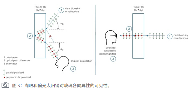
Figure 3. Visibility of glass anisotropy under normal vision and through polarized sunglasses.In addition, several technical parameters influence anisotropy intensity:
- Glass thickness
- Number of glass layers
- Panel size
- Glass geometry complexity
- Interlayer materials in laminated glass
Large panels or glass with complex shapes—such as sharp corners, cutouts, or drilled holes—are generally more difficult to temper without producing noticeable anisotropy.
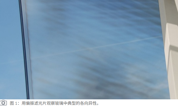
Figure 1. Typical anisotropy pattern (leopard spots) observed in tempered glass under polarized light.
Measuring Anisotropy in Tempered Glass
Modern online anisotropy scanners allow manufacturers to measure optical anisotropy quantitatively during production. These systems use polarimetric measurement principles combined with telecentric light sources emitting multiple wavelengths. By analyzing image‑based data, the scanner calculates the optical path difference for each pixel across the glass surface using the stress‑optical law. The measured optical retardation provides a numerical indication of the residual stress distribution and the likelihood of visible anisotropy across the panel. However, certain surface conditions—such as coatings or glass dust—may interfere with measurement accuracy because they absorb or reflect light.
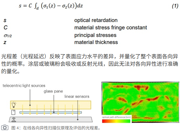
Figure 4. Working principle of the online optical anisotropy scanner and optical path difference measurement.
Evaluation According to International Standards
Current standards for heat‑treated glass—including EN 1863, EN 12150, EN 14179, and ASTM C1048—describe anisotropy as stress patterns that may become visible under certain lighting conditions. Importantly, these standards emphasize that anisotropy is a characteristic rather than a defect. Guidelines such as DIN SPEC 18198 and ASTM C1901 provide methods for measuring and evaluating optical anisotropy. DIN SPEC 18198 defines two main evaluation methods:
- Method A: Uses the 95th percentile optical retardation value (X95) to represent anisotropy across the evaluated area.
- Method B: Calculates the percentage of surface area with optical retardation below 75 nm, known as Iso75.
Research shows that 75 nm is approximately the threshold where anisotropy becomes visible to the human eye. Based on these measurements, glass can be classified into Quality Classes A, B, or C. However, even glass meeting Class A requirements may still display visible anisotropy patterns in certain lighting conditions.
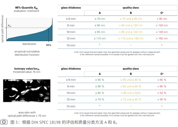
Figure 5. Anisotropy evaluation according to DIN SPEC 18198: Method A (X95) and Method B (Iso75) and quality classification.
Advanced Technology for Low‑Anisotropy Glass
To meet the architectural demand for perfectly uniform glass facades, new tempering technologies have been developed to significantly reduce visible anisotropy. These technologies focus on:
- More uniform heating inside the tempering furnace
- Optimized air‑cooling systems
- Advanced process monitoring
- Improved stress distribution control
With these improvements, the optical retardation values of tempered glass can be reduced well below standard limits, making anisotropy virtually invisible to the human eye. Additionally, coatings can be applied either before or after the tempering process, allowing designers to combine excellent optical clarity with functional performance such as solar control or thermal insulation.
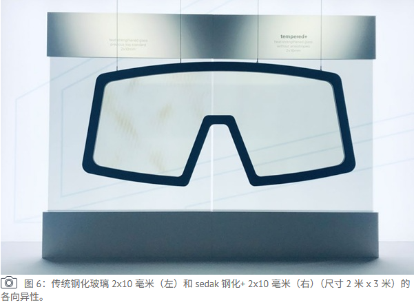
Figure 6. Visual comparison of anisotropy between conventional tempered glass and advanced low‑anisotropy tempered glass.
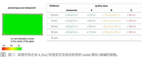
Figure 7. Anisotropy test results (Method A) for high‑performance low‑anisotropy tempered glass, showing values far below the visibility threshold.
Curved Glass Without Visible Anisotropy
Producing curved tempered glass without visible anisotropy remains technically challenging. Compared with flat tempering furnaces, bending tempering furnaces require higher temperatures and more complex cooling systems, which can increase stress concentrations.To overcome this challenge, manufacturers increasingly use alternative methods such as:
- Cold Bending: Glass is mechanically fixed into the required curved geometry during installation.
- Laminated Bending: Flat tempered glass panels are laminated in an autoclave using structural interlayers that hold the desired curved shape.
These methods enable the production of large curved glass panels with excellent optical quality, while maintaining the mechanical strength of tempered glass. Bending stress can be estimated by:σ=2rE⋅t
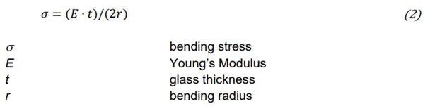
Figure 10. Bending stress formula and key parameters for curved glass design.
With advanced engineering analysis—including finite element modeling (FEM)—architects can design curved glass structures with dimensions up to 3.6 meters × 20 meters.
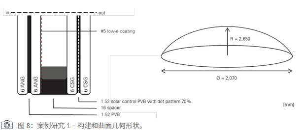
Figure 8. Case study 1: Curved glass facade application with low‑anisotropy glass.
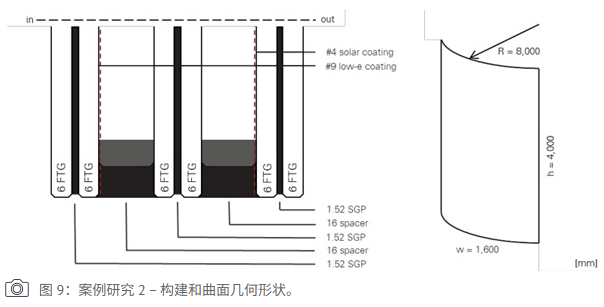
Figure 9. Case study 2: Complex curved glass geometry and laminated bending structure.
Conclusion
Eliminating visible anisotropy in architectural glass represents a significant advancement in modern glass processing technology. Through improved tempering techniques, advanced measurement systems, and innovative lamination methods, manufacturers can now produce both flat and curved glass panels with outstanding optical clarity. These developments enable architects and engineers to create large, visually flawless glass facades without compromising structural performance. As manufacturing technologies continue to evolve, the architectural glass industry will gain even greater freedom in design, scale, and performance, opening new possibilities for future building projects.